 |
Segmented TurningDesign your first segmented project in 5 minutes with the Segmented Project Planner |
|||
|
| Products | Classes | Free Plans | Hints | Buy Now | Gallery | Wood Costs | User Projects | FAQ |
The Segmented Project Planner will help you spend less time doing the planning and drawing and more time where the fun is; at the lathe. Here are some of the details...
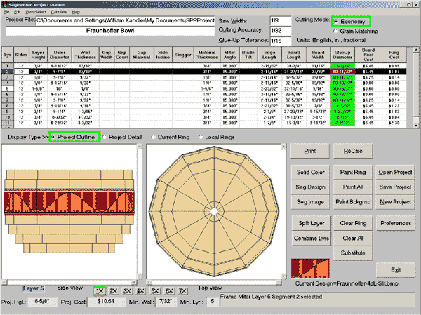
The project in the picture below is a bowl featuring a band of Fraunhoffer diffraction patterns around it. I've used a .bmp file drawing to paint the pattern around the bowl. The band will be fashioned using my scroll saw to cut the pattern from a stack of two different wood colors so that they nest into a single thickness of wood. The project is being displayed at the 1X zoom level and layer 2 is currently selected. You can see all of the specifics of layer 2 in the grid. You can change the number of sides, outer diameter, or wall thickness of the layer in the grid, and the results of the change are immediately displayed. Just off the bottom-right corner of the top view of the project, the current color patch shows a sample of the image file that was used to paint all the segments in layer 5 of the bowl.
 |
You can download the program's installation package right now for a free, 30 day trial. It's the complete program with printing limited to the first 5 layers of your project. As soon as you purchase the program and register, the program will print your complete project. Just Click Here to start the download of Segmented Project Planner. You'll like what you see. As of today, 5735 people have purchased it. If you decide later to purchase the program. Do not download and install again after the purchase. Just register using the information I'll send you. |
When you print the project, you get all the segment dimensions in a tidy report you can take to the shop. For a project that uses Named Colors or Segment Designs/Mosaics to fill segments, the report details the count, sizes, and cutting angles for all the components of the project. Click Here to see a sample report for a project using Segment Designs. For a project that contains vertical spacers or open segment layers, the report details the spacer or open segment information.
What data/measurements do you need to get started? Actually it’s not much. The essential pieces are the thickness and diameter of each layer along with the number of sides and the width of the layer’s ring. With these items you can define any frame miter or stave ring. Add the side incline angle and material thickness to the mix to define a compound miter situation.
You can make a drawing on a quad pad or use a simple drafting program to start the design. Then get out your ruler or use the drafting program’s dimensioning capability to measure off the necessary dimensions. Or, you can wing it and do the entire design process within the program itself. For this sample project I used Sketch-A-Bowl to establish the basic shape, then used the Layer Tuner to refine it, and AutoBowl to set up for my desired wall thickness. This sequence was my standard practice with occasional trips to the Sketch Pad when I couldn't get what I wanted in Sketch-A-Bowl. Now I do it all in Shape-A-Bowl.
To manually start the definition of each ring in the program, just click on the blank row at the bottom of the grid display to add the ring to the bottom of the project or use Ctrl I to add the new ring above the current ring. The program will add a new layer and pre-fill it with the essential values from the row above/below and will even try to anticipate the size of the new ring based on the rings already there. You can replace values as necessary. You can supply the board foot cost of your materials if you’re interested in the project cost.
You can select a ring either by clicking on it in the Side view or by clicking in its row in the grid display. The Project Outline view is currently shown in this example.
The File menu includes New, Open, Save, Save As, Print, Printer Setup, Delete, and Exit commands for full control over your developing project file. Recent additions to this menu include controls for printing segment and ring templates and generating the project document.
The Edit menu includes Undo, Cut, Copy, Paste, Insert, ReCalc, Clear Colors, Paint All, Copy Layers, Preferences, and the designers for Open Segments and Vertical Spacers. Recent additions here include painting the current ring, painting all unpainted segments to a background color, and editing of project document parameters. These all make it easy to manipulate each layer of your project.
The View/Select menu provides access to the Project Gallery, Layer Tuner, Color Picker, Segment Designer, Segment Images, Sketch-A-Bowl, the Template Printer, and the project document.
The Calculate menu provides access to AutoBowl, the Incline Angle Calculator, and Project Resize.
For even more details on what/how the program does/works, click here to view the Segmented Project Planner help file system.
